How to use your own virtual firewall with Copaco VMware Cloud
Summary
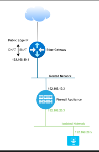
In some cases you want to deploy your own virtual firewall. It is not possible to have a direct internet connection to your virtual firewall since the edge is the demarcation point.
This article describes how you can use your own virtual firewall behind the Copaco VMware Cloud edge.
Prerequisites
An active Copaco VMware Cloud subscription;
Deployed the virtual appliance.
Getting Started
This article is divided into 5 parts. You may use the ‘on this page’ section to skip to a different part easily.
Creating required networks
To correctly do this, two Copaco VMware Cloud networks need to be created.
WAN network: this network is a routed network and only used for the connection between the virtual firewall and edge.
LAN network: this network is a isolated network and used for LAN traffic and is used for the VMs behind the virtual firewall.
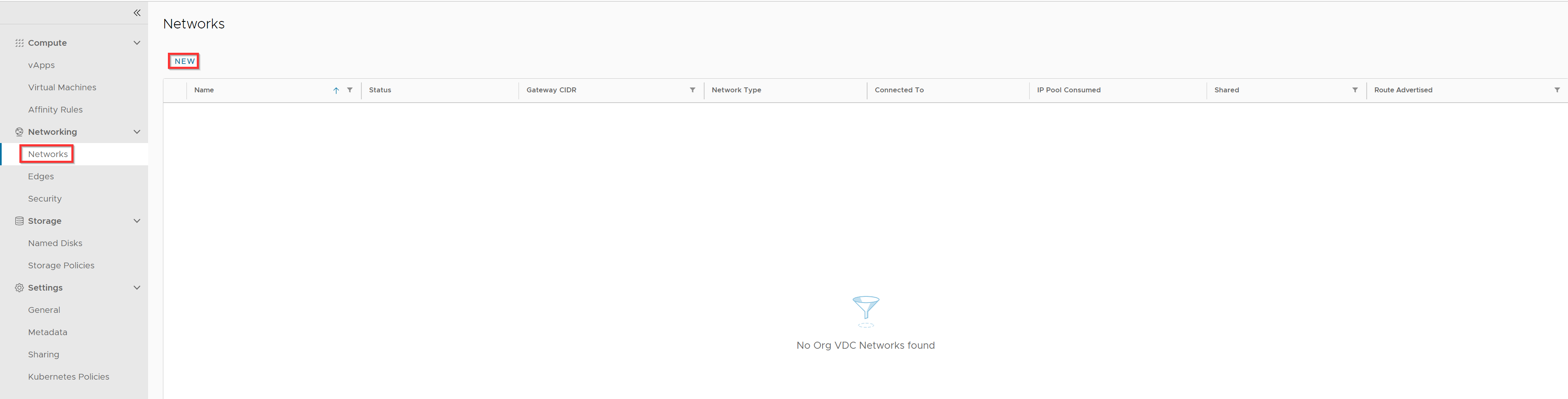
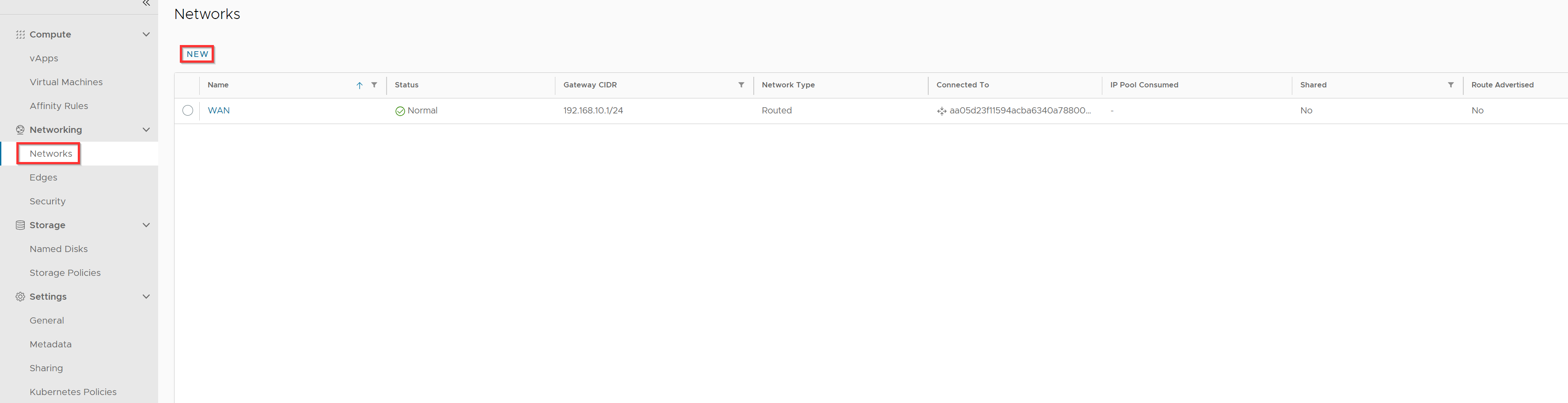
Click Networks and click New.
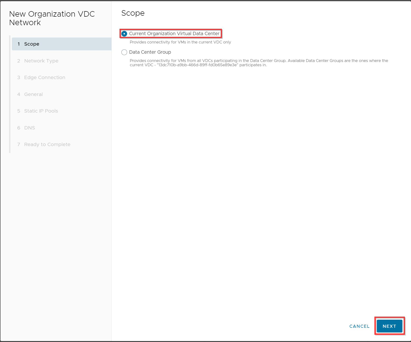
Select Current Organization Virtual Data Center and click Next.
Select Routed and click Next.

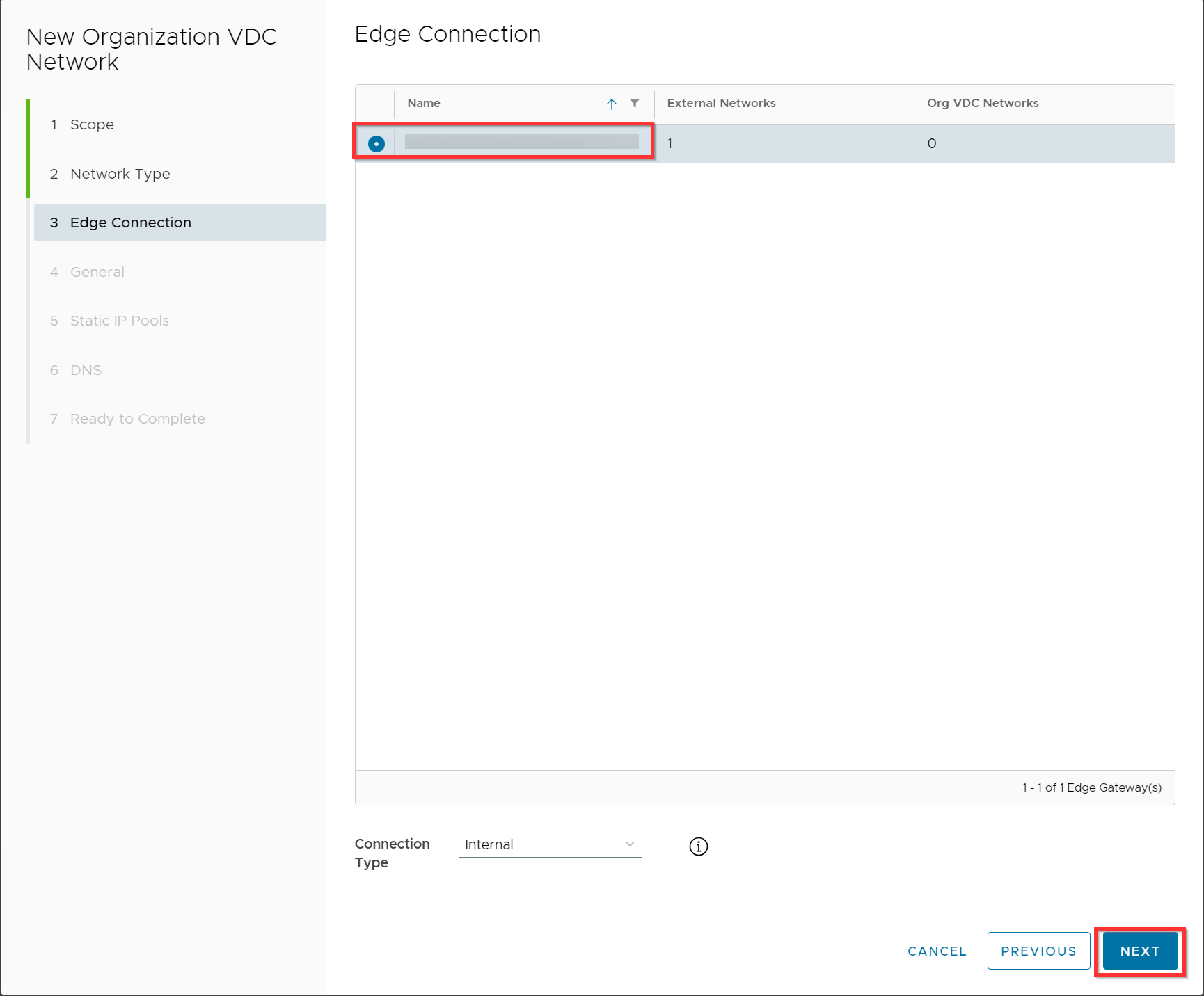
Select the edge and click Next.
Enter the name “WAN”, fill in the gateway CIDR and click Next.
In this example we will use the 192.168.10.0/24 subnet with a gateway address 192.168.10.1.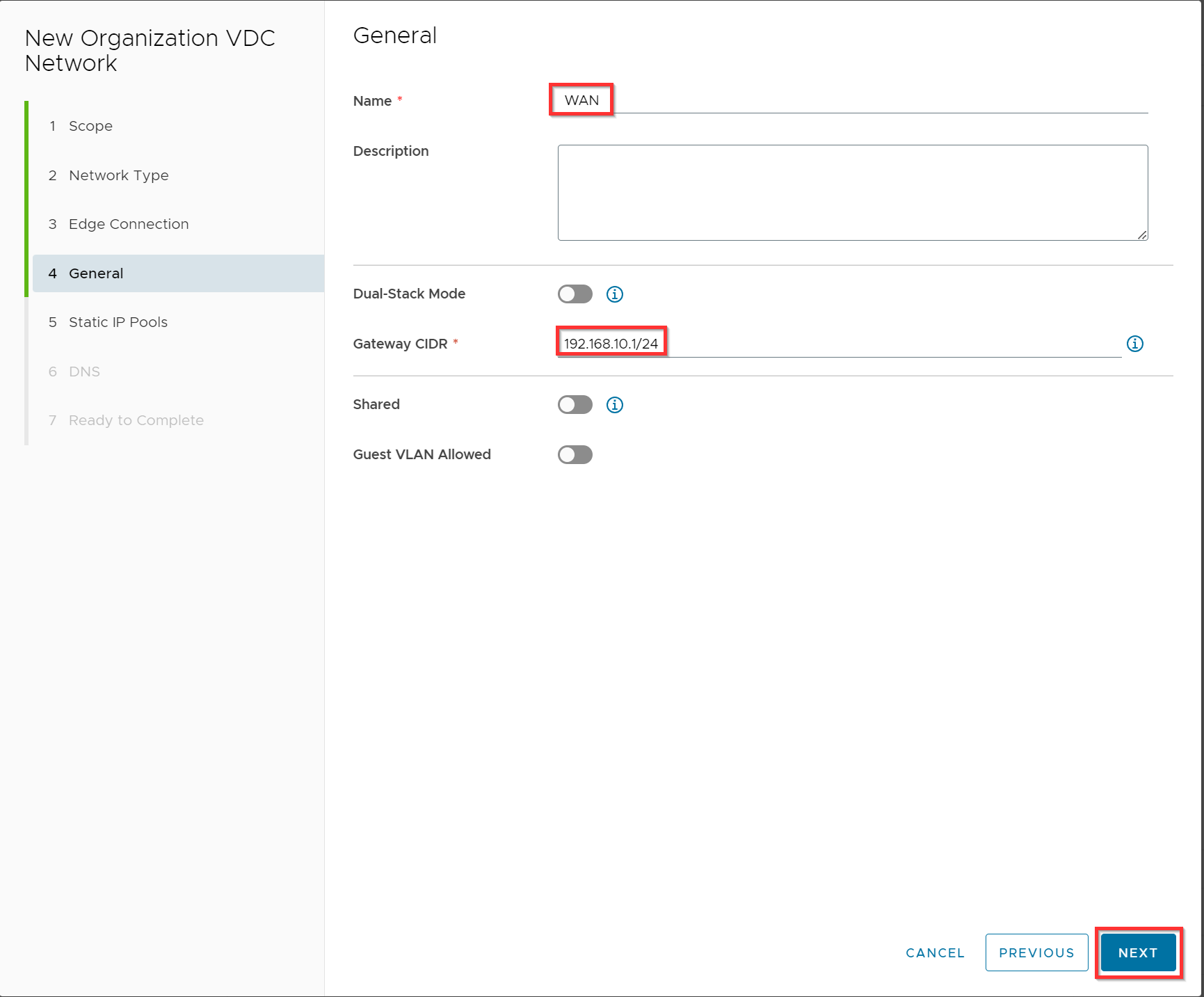
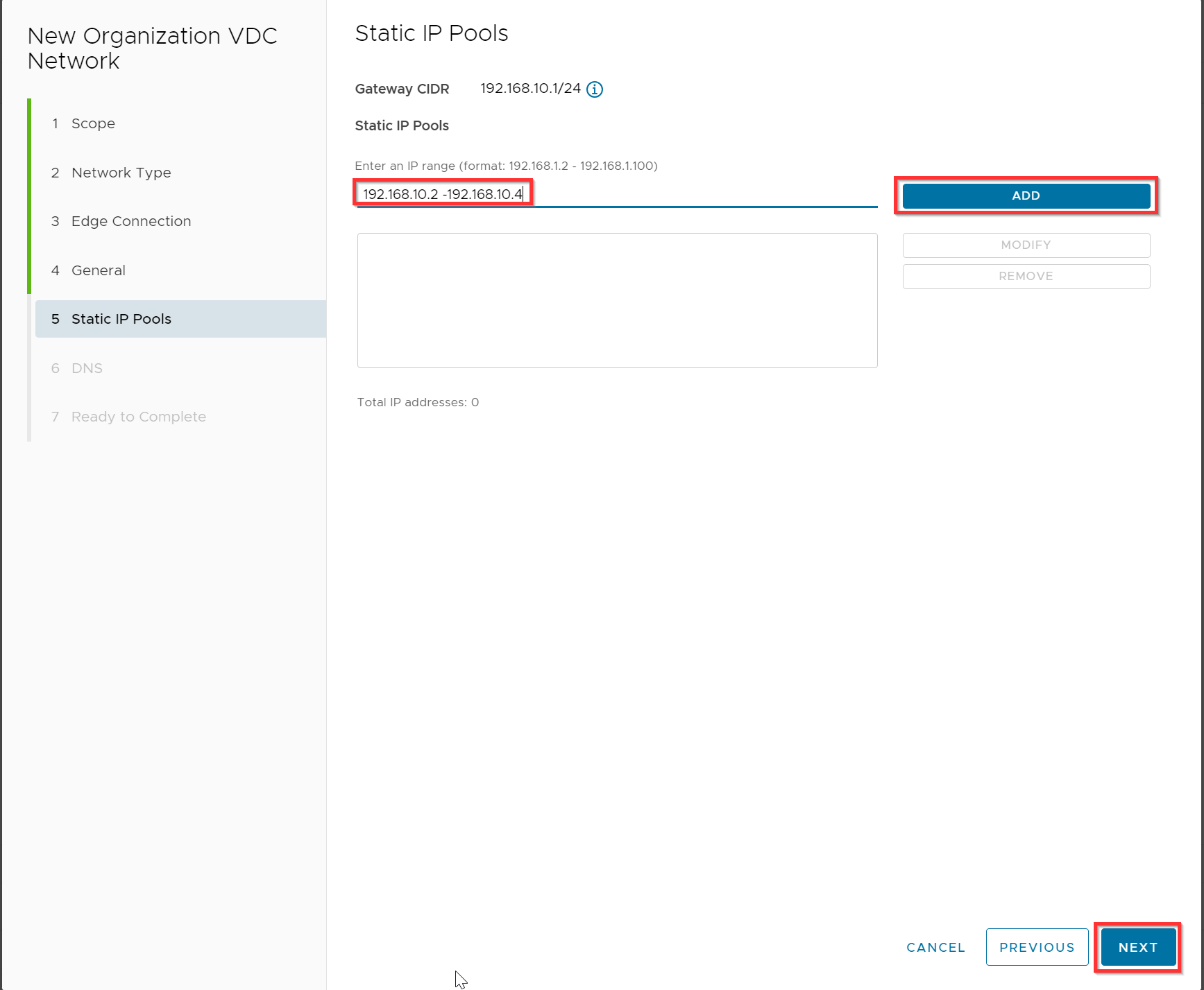
Optional you can use an IP pool 192.168.10.2 -192.168.10.4 since only the virtual firewall will be a member of this “WAN” network. Click Add and Next.
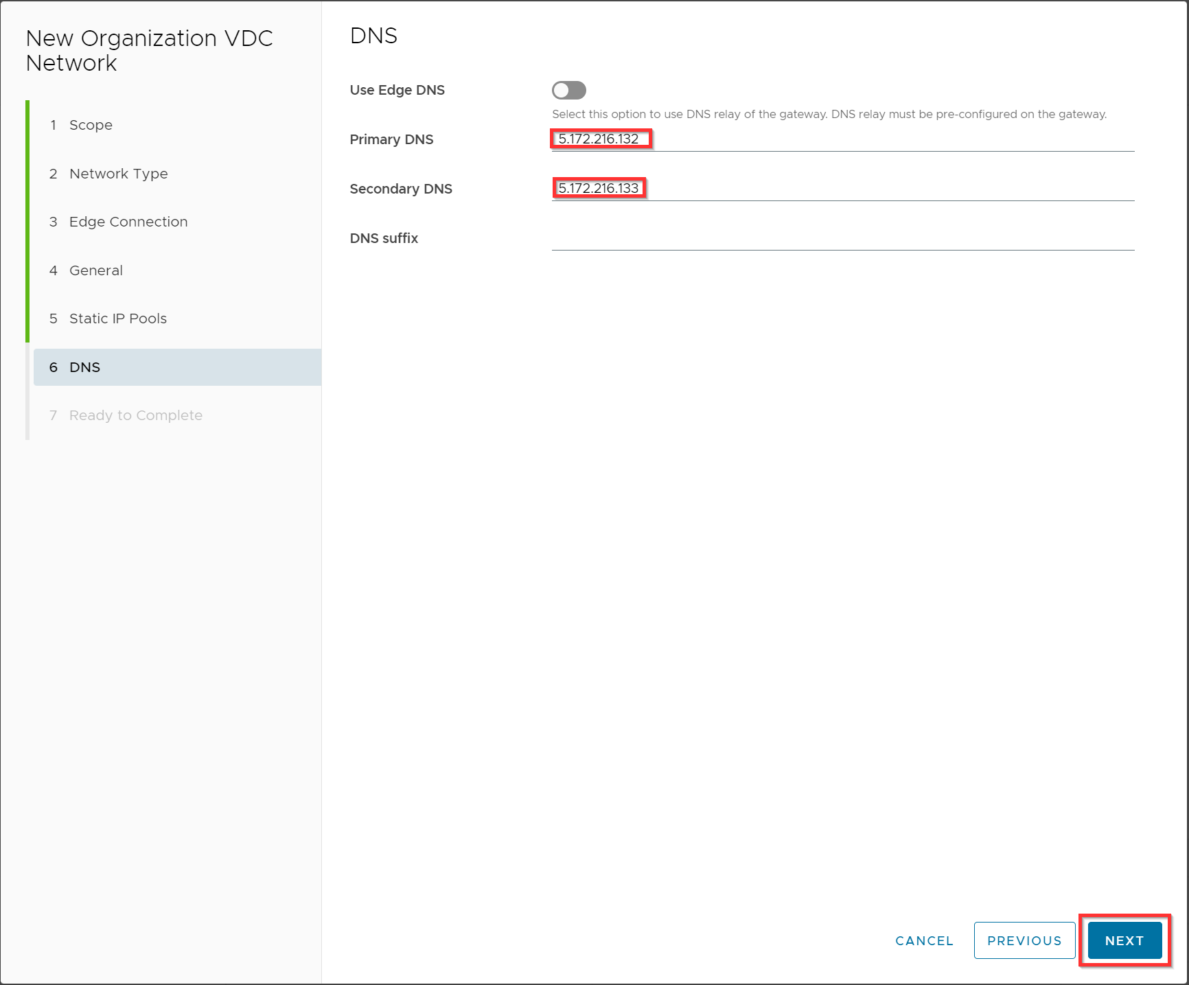
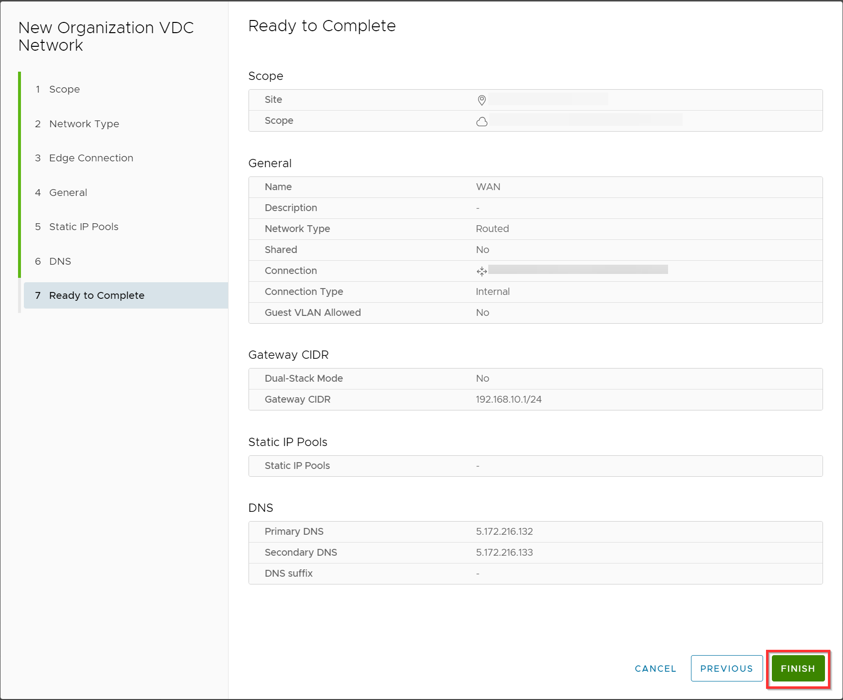
Untick “Use Edge DNS” and specify your DNS servers (you can also use other public DNS servers) and click Next.
Review the configuration and click Finish.
Now we will to create the LAN network.Click on Networks, and click New.
Select Current Organization Virtual Data Center and click Next.
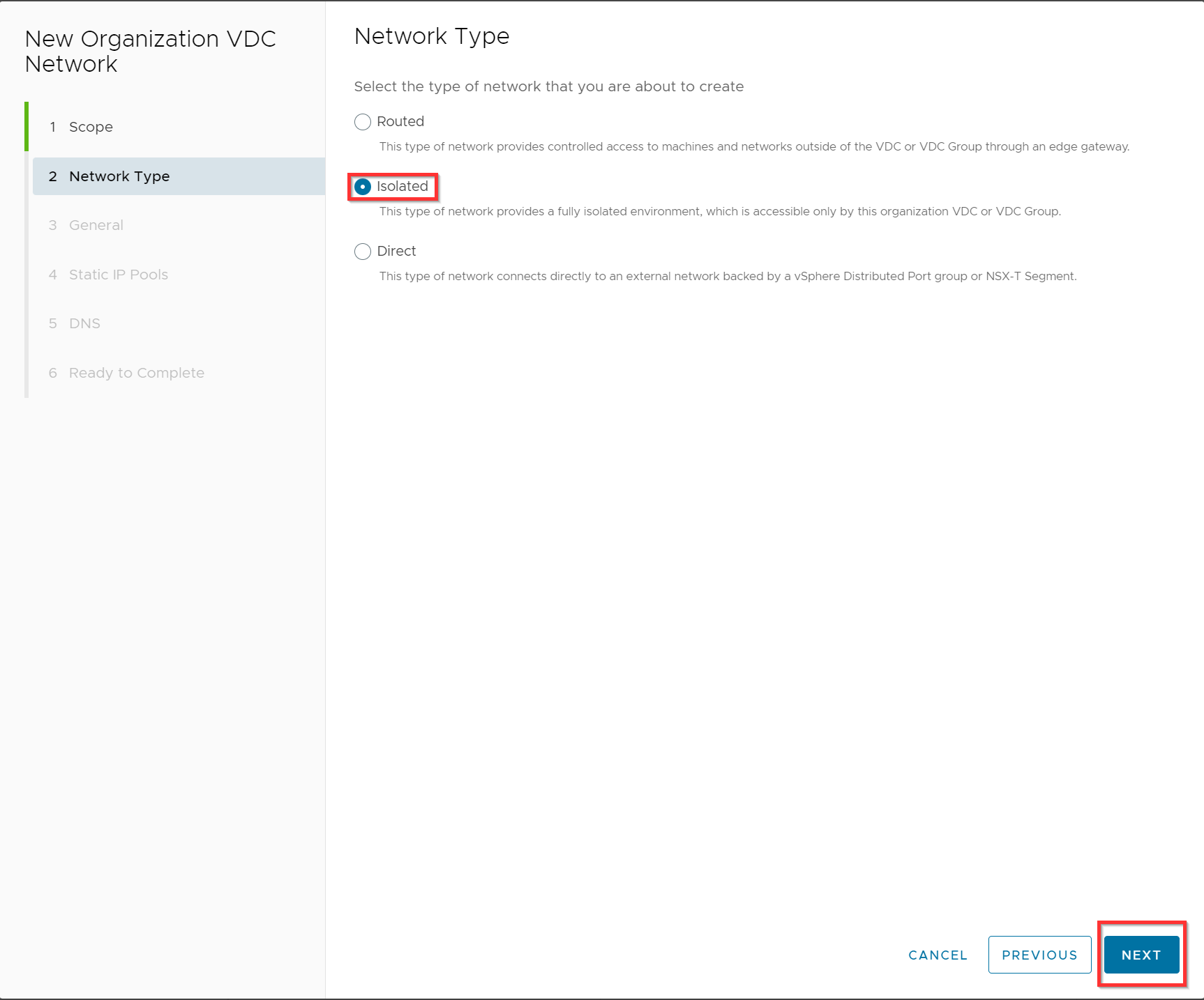
Select Isolated and click Next.
Enter the name “LAN”, fill in the gateway CIDR and click Next.
In this example we going to use the 192.168.20.0/24 subnet with a gateway address 192.168.20.1.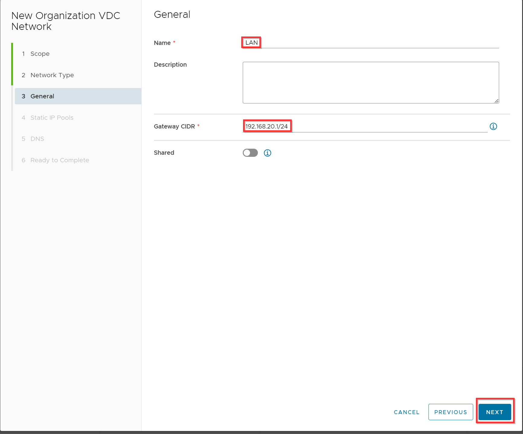
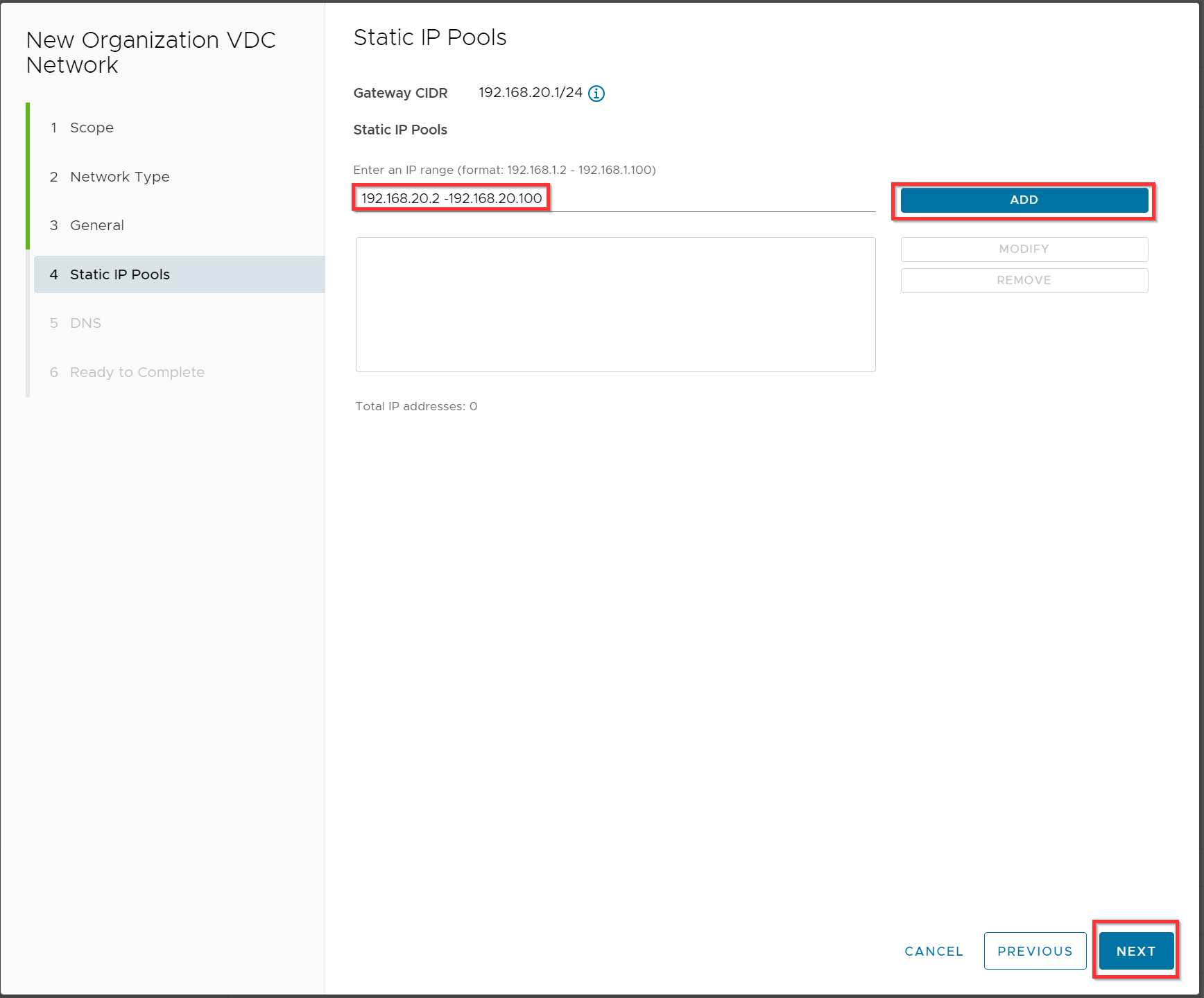
Optional you can use an IP pool 192.168.20.2 -192.168.20.100 where the virtual firewall will be a member together with all other VMs of this isolated LAN network. Click Add and Next.
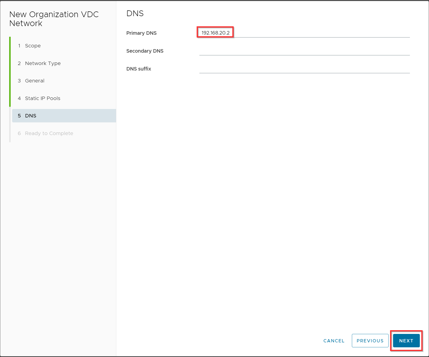
Optionally: Specify your DNS server and click Next.
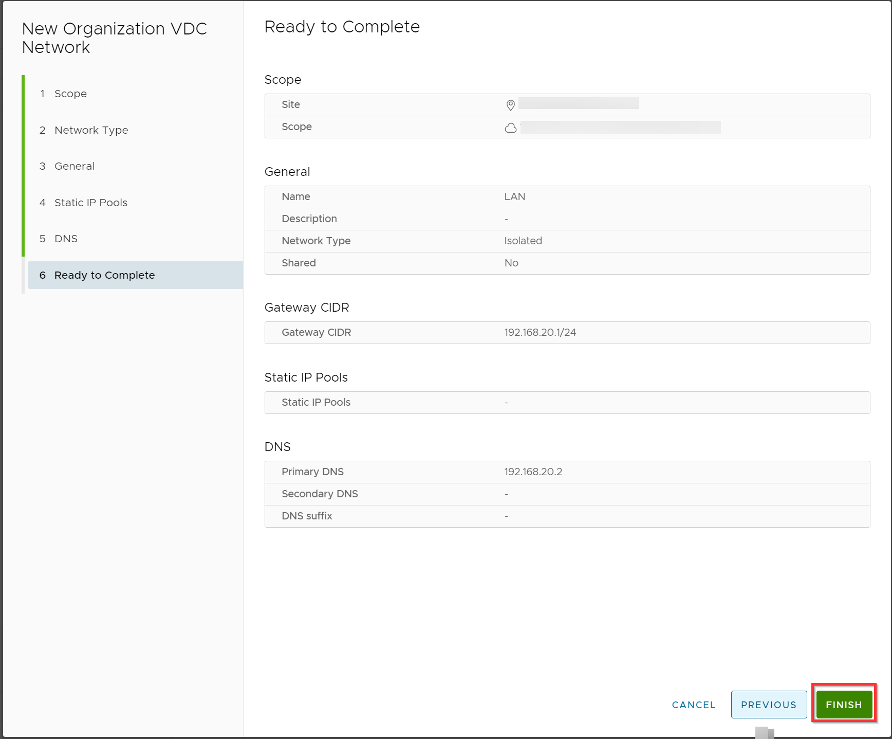
Verify the configuration and click Finish.
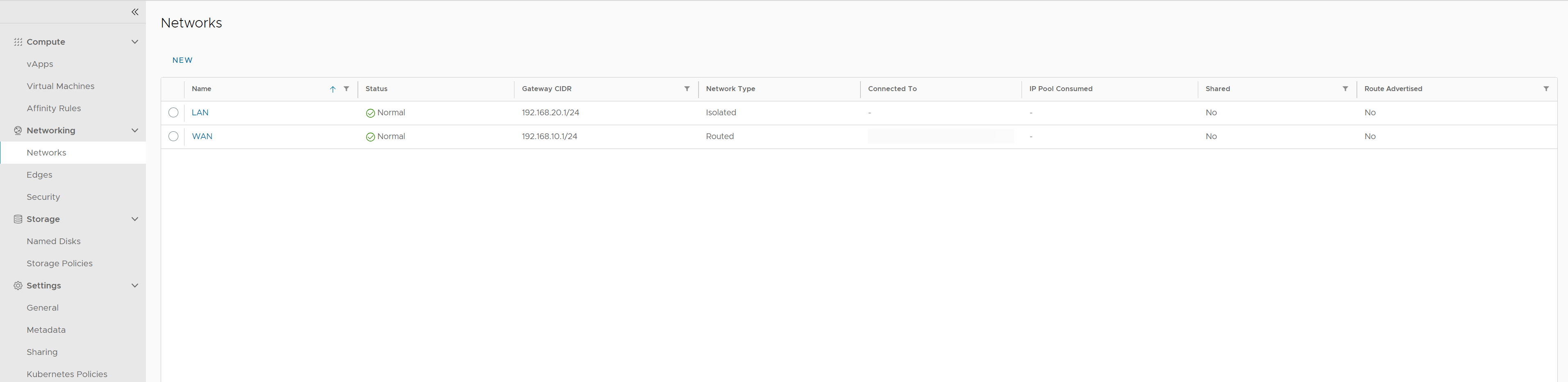
The two networks are created.
Connecting the networks
Now the networks are created, both the LAN and WAN networks need to be connected to the virtual firewall. The LAN Network also needs to be connected to the VMs.
In this example we are going to assign the IP address for the virtual firewall WAN interface 192.168.10.3 and for the LAN interface 192.168.20.3. For the VM LAN interface we are going to use the 192.168.20.4
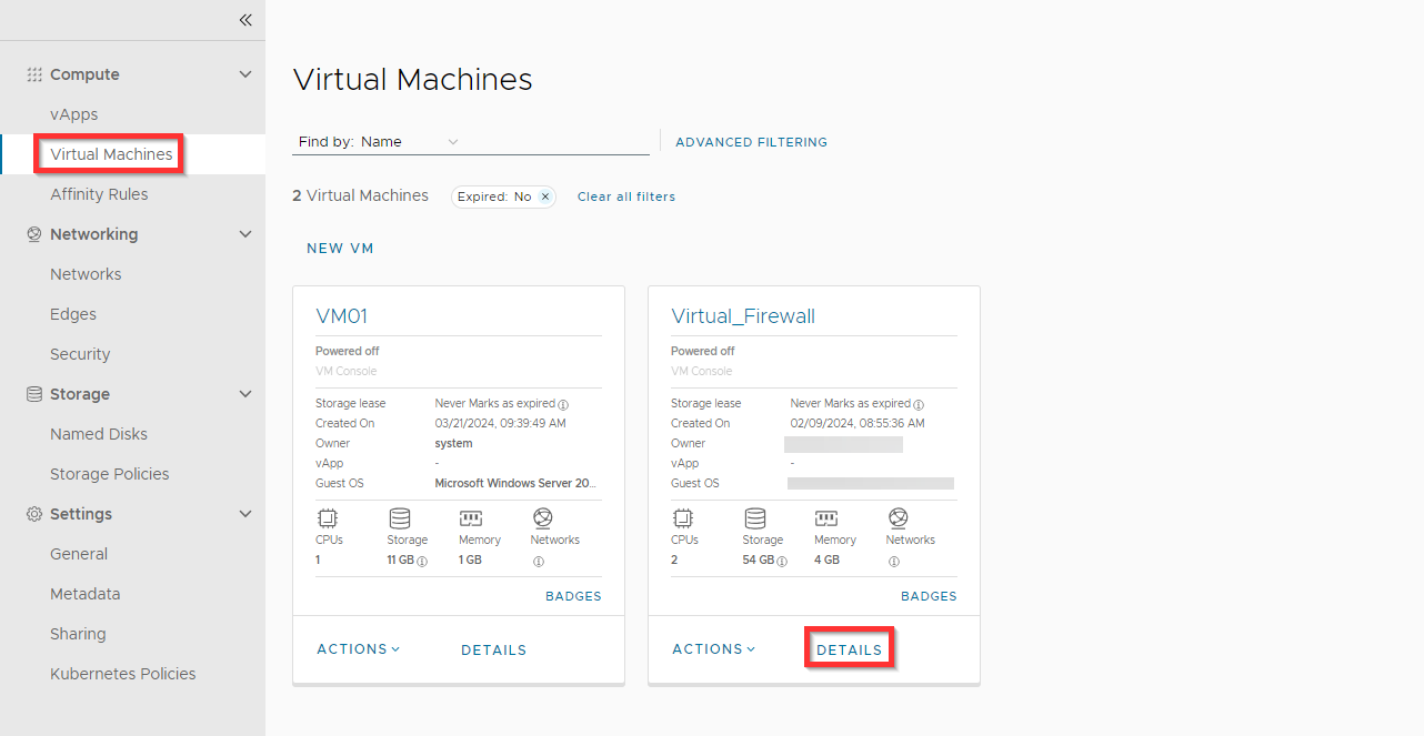
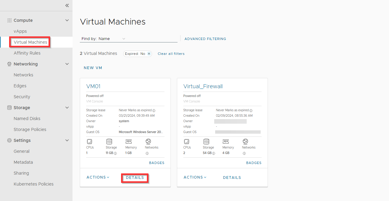
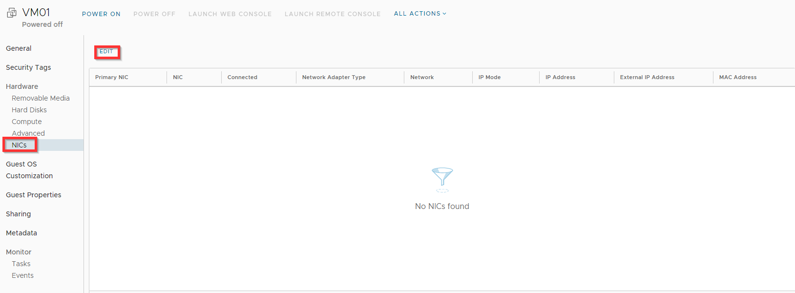
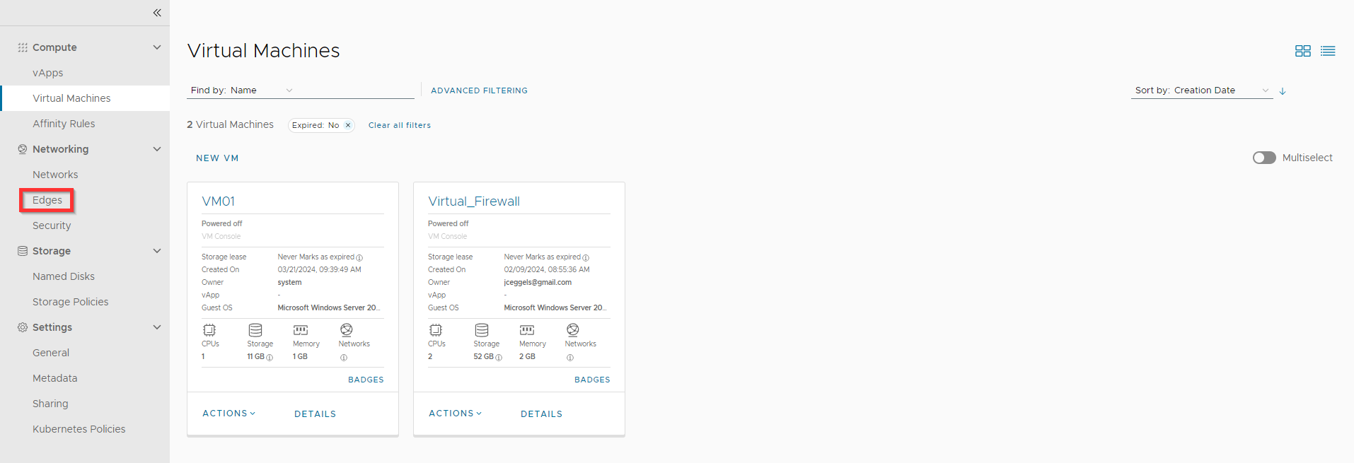
Go to Virtual Machines and click on DETAILS for the virtual firewall.
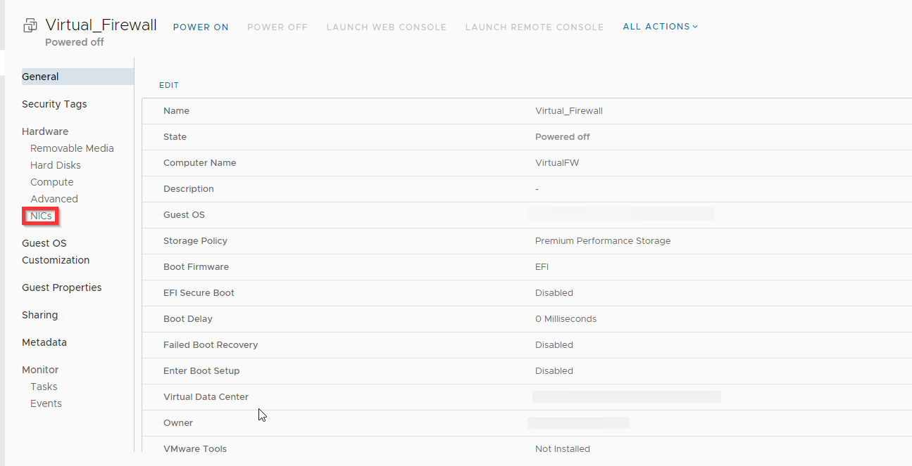
Click NICs.
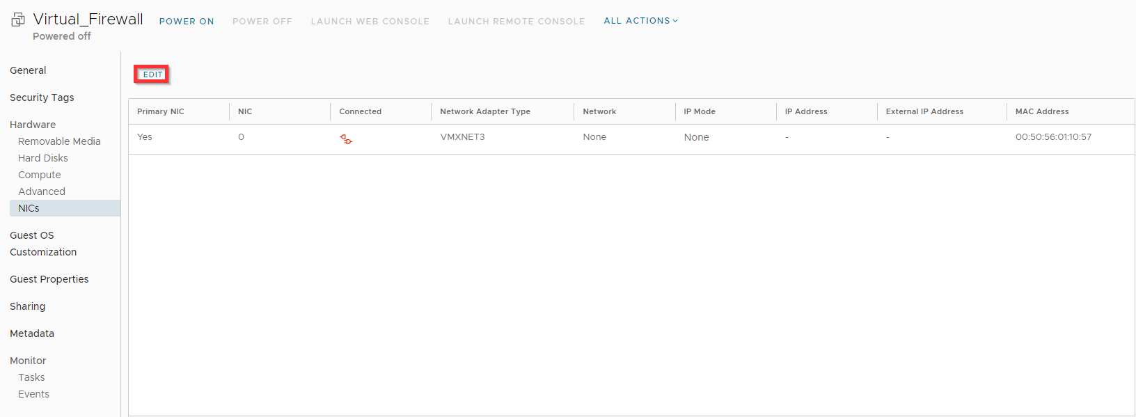
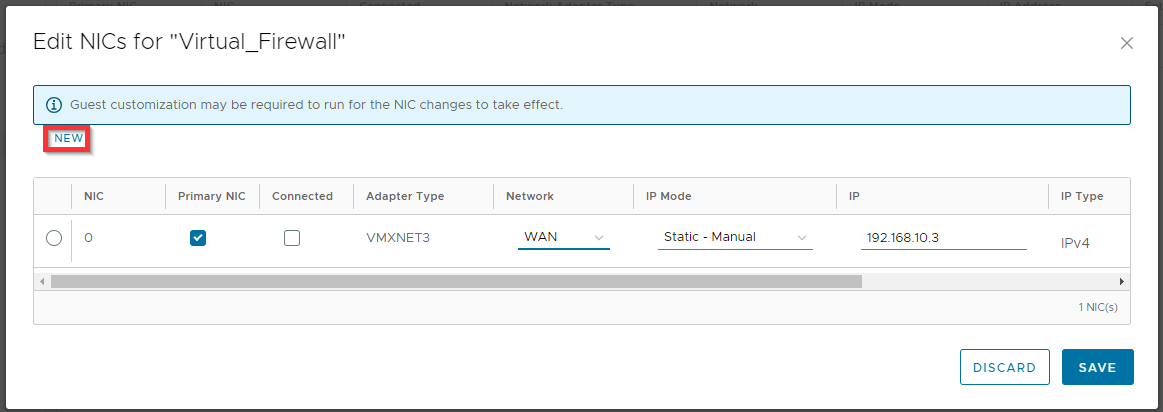
Click Edit.
Change the Network, IP Mode and IP settings for the WAN network and click Save.
Adapter Type VMXNET3 (only if it is supported by vendor; check vendor documentation, otherwise you can choose E1000E)
Network WAN
IP Mode Static - Manual
IP 192.168.10.3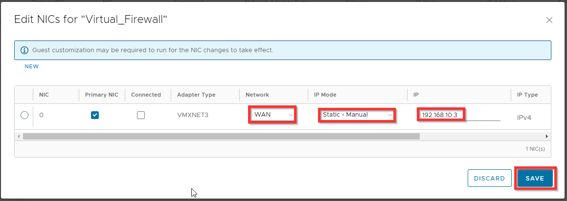
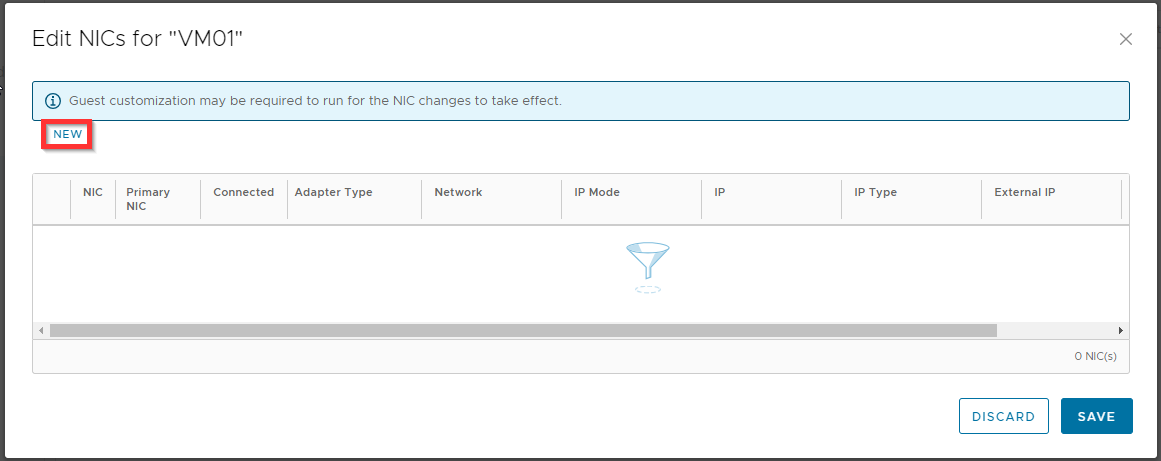
.Click New.
Change the Network, IP Mode and IP settings for the LAN network and click Save.
Adapter Type VMXNET3 (only if it is supported by vendor; check vendor documentation, otherwise you can choose E1000E)
Network LAN
IP Mode Static - Manual
IP 192.168.20.3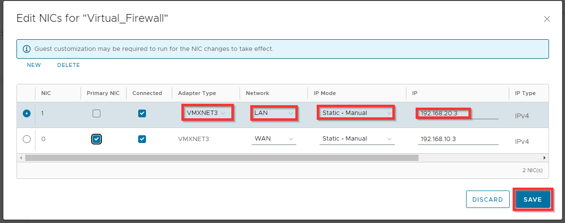
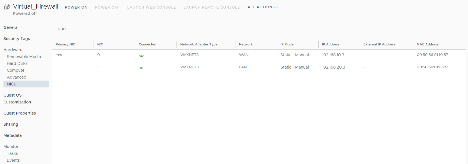
The networks are attached to the Virtual_Firewall.
Go back to Virtual Machines and click on DETAILS for the VM.
Click NICs, and click Edit
Click New (or edit).
Change the Network, IP Mode and IP settings for the VM and click Save.
Here yo need to specify the following:
Adapter Type VMXNET3
Network LAN
IP Mode Static - Manual
IP 192.168.20.5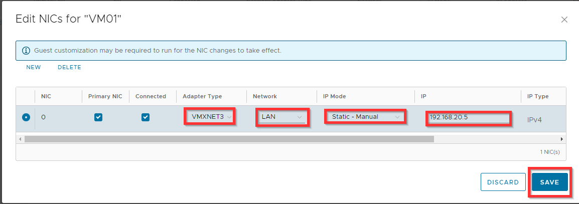
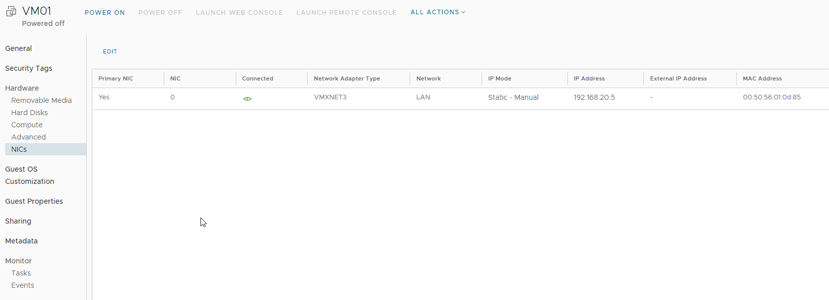
Now the network is attached to the VM.
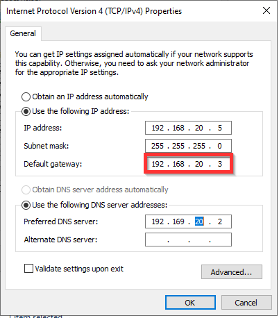
Configure NICs
After the WAN and LAN networks are connected, they need to be configured. Configuring them depends on the type and vendor used. For the WAN interface you should select the interface which is created during the network creation, which in our example is: 192.186.10.3 and for the LAN interface it should be 192.168.20.3.
On the VMs you must specify the LAN interface IP address of the virtual firewall as the gateway.
Creating Edge Firewall Rules
Now you need to create the following Edge Firewall Rules;
A Rule to forward all the traffic from the edge to the Virtual Firewall.
A Rule to forward all the traffic from the Virtual Firewall to the Edge.
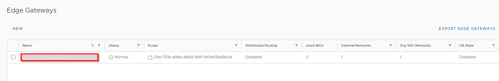
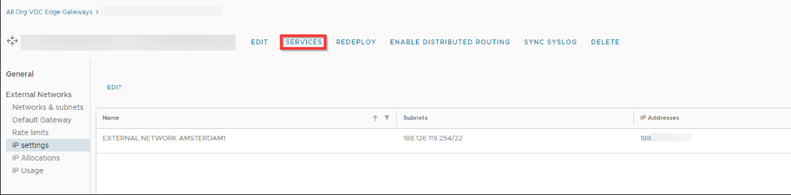
Click Edges.
Click on the name of the edge.
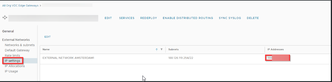
Click IP settings and write down the IP address under IP addresses, you need this during configuration of the firewall rules.
Click SERVICES.
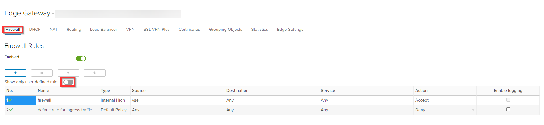
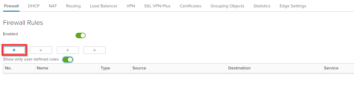
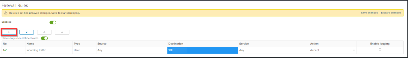
Click on Firewall and toggle Show only user-defined rules ON.
Click the + sign.
Create a firewall rule with the following settings and click Save changes.
Name incoming traffic
Source Any
Destination the IP address that you have found in step 3
Service Any
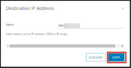
Action AnyClick in destination column on IP.
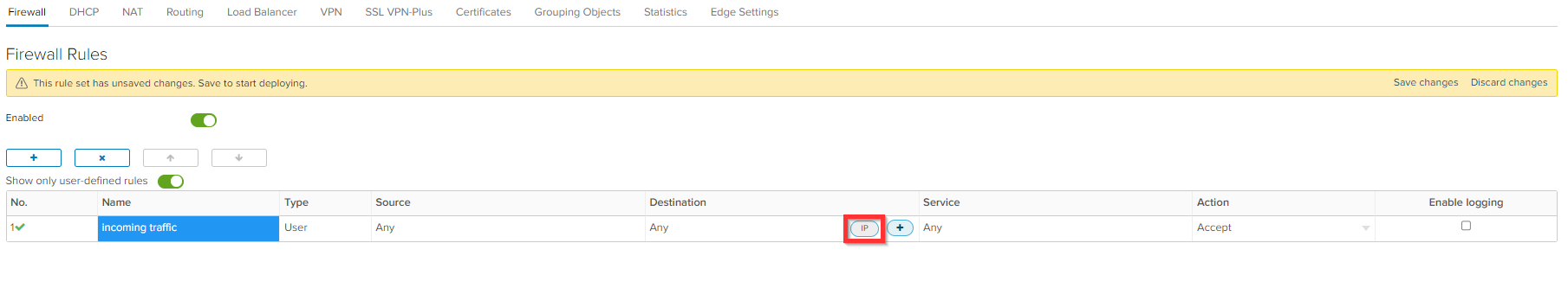
Enter the IP address and click Keep.
Click the + sign to add the outgoing rule.
Create a firewall rule with the following settings and click Save changes.
Name outgoing traffic
Source WAN IP from the virtual firewall (192.168.10.3)
Destination Any
Service Any
Action Any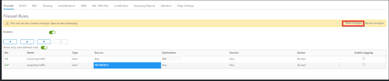
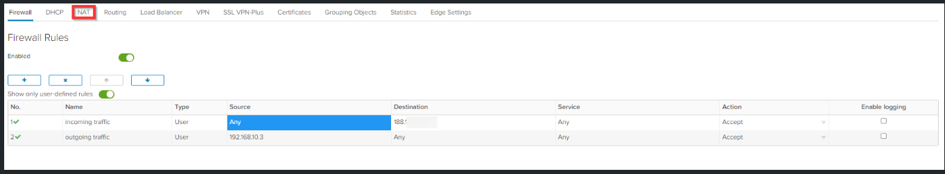
Configuring the Edge NAT Rules
Now you need to create the following NAT rules;
A Nat rule that will NAT all incoming traffic to the Virtual Firewall
A Nat rule that will NAT all outgoing traffic to the Edge
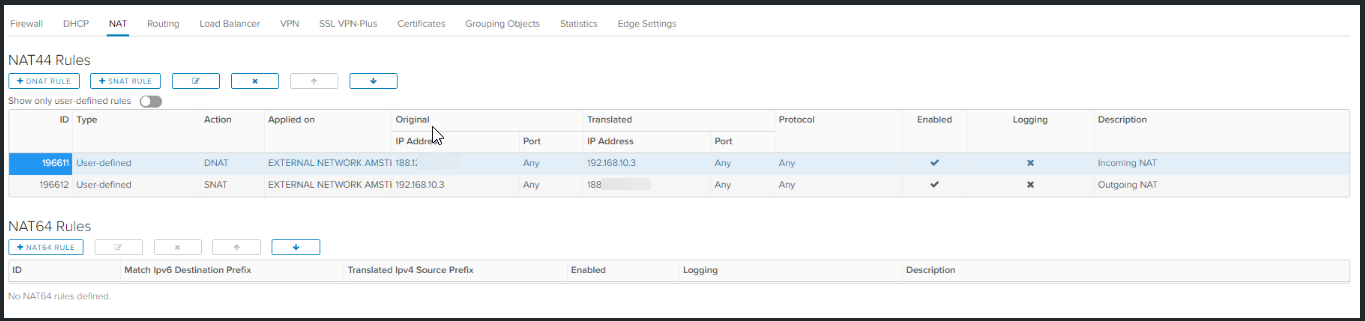
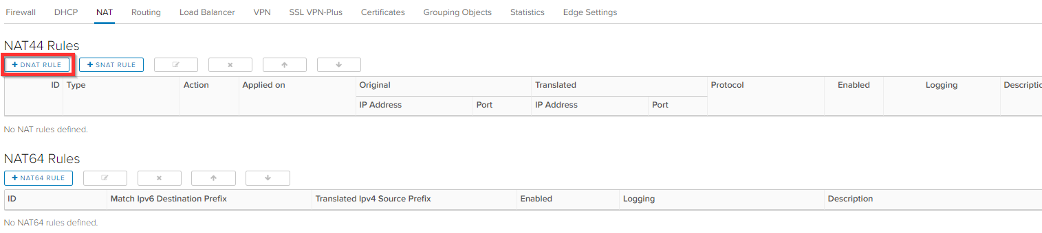
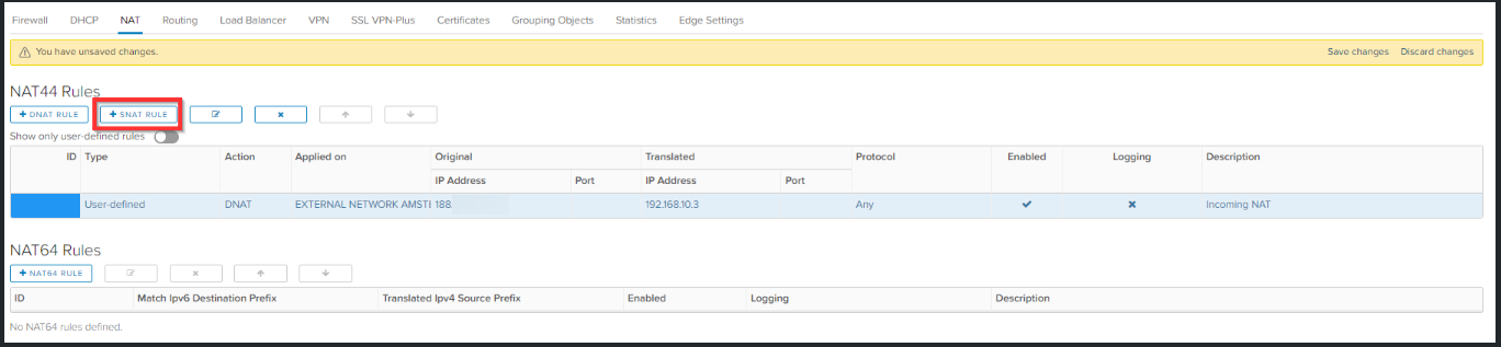
Go to NAT.
Click on + DNAT Rule
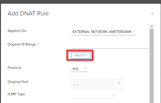
Click SELECT to select the edge IP.
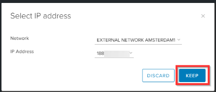
Click KEEP.
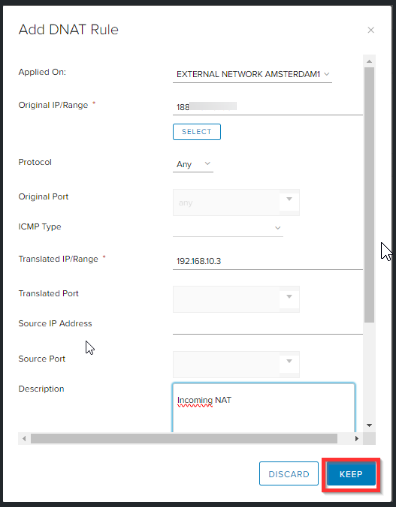
Specify the WAN IP from the virtual firewall (192.168.10.3) as Translated IP and give it a description. Click KEEP.
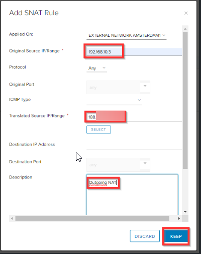
Click on + SNAT Rule for creating the outgoing NAT rule.
Specify the WAN IP from the Virtual Firewall as Original Source IP and select the public IP from the edge as translated source IP and click KEEP.
Click Save changes.
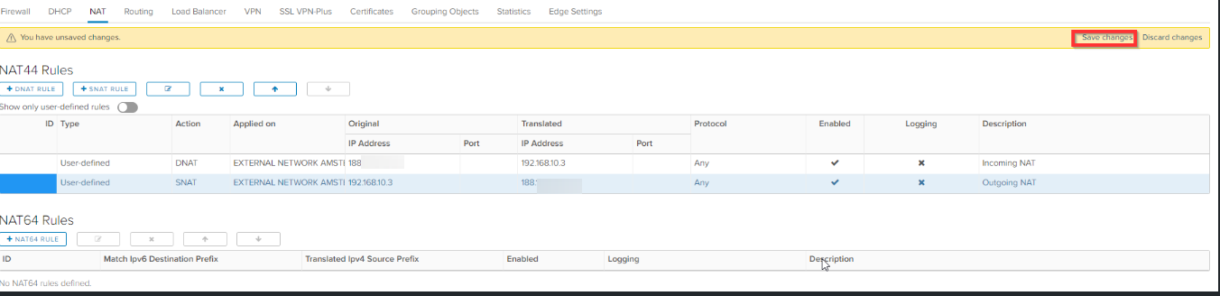
The incoming and outgoing traffic is now going through your own virtual firewall.